All measurements are correct. Here the filter is turned on, showing significant smaller signal due to the filter blocking the higher frequency harmonics. The counter does not have any decoupling capacitors connected to it, hence the very noisy power line. The scope clocks it at 3. My main criteria was that the oscilloscope should have: 
| Uploader: | Tygotaxe |
| Date Added: | 4 December 2010 |
| File Size: | 67.4 Mb |
| Operating Systems: | Windows NT/2000/XP/2003/2003/7/8/10 MacOS 10/X |
| Downloads: | 19381 |
| Price: | Free* [*Free Regsitration Required] |
QB - Atten 25MHz LCD Digital Storage Oscilloscope - Altronics
Same 66MHz signal showing the configuration of the digital filter. The Ref scale is correct for a 1X probe configuration.
It correctly measures the phase shift as well as the FRR time between the two waveforms. It must be noted that the scope does not allow measurements on the resulting math waveform but neither does the Rigol or the HP.
Back to a 4MHz signal measured directly on the output pin of a 4MHz crystal oscillator can. Back to measuring the 1kHz calibration wave along with a few measurements added on the measurement bar. The 64MHz signal divided by two using the on a breadboard.
The counter does not have any decoupling capacitors connected to it, hence the very noisy power line. For years I have been using my trusty PicoScope for my electronics hobby needs. This really is not an issue though.
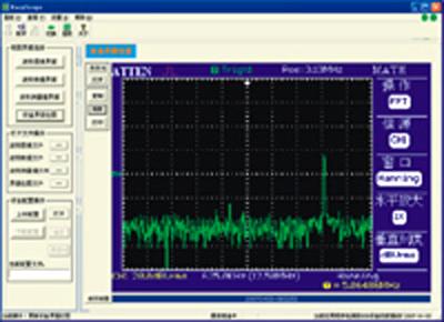
The Hz peak stands out between the two cursors. The output of the crystal oscillator is actually a square wave, but the harmonic frequencies are far higher than what the scope can measure, so the display is correct. It arrived here in South Africa two eaysscope later.
The rise time is correctly measured at 3. Note that, for the most part, the scope correctly plots the waveform and shows the noisy state of the oscillator output. Using the same oscillator, I switched the scope to EquTime mode and was presented by the screen to the left.
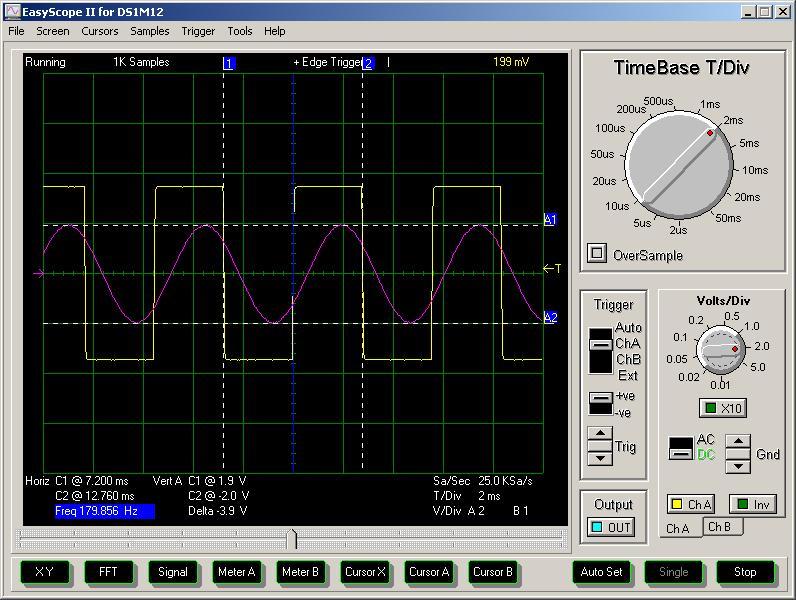
Cursor A is adjusted to 0Hz on the left and Cursur B is adjusted to the second harmonic at 1kHz on the right. In contrast, the fan on the Rigol DSE is really rather loud and disturbing. The probe was set to 10X for better freq. Fixes are shown in blue below. The power cord is plugged into the back of dasyscope oscilloscope, not the side.
I've read reports of the Siglent scopes not triggering correctly at low voltages on the down slope, but I could not simulate the problem at any frequency. Testing the acquisition system with a 1MHz signal and triggering on the down slope. Things that annoy me about the scope. Here we have the 15kHz signal again, showing noise generated on the power line of the supply to the 74HC binary counter.

This is by no means a comprehensive review, but I will try to give a fair overview of the scope's performance. Horizontal FFT frequency scale is incorrect when Long Memory mode is selected Averaging sampling does not work at all.
No matter what I did, I could not get the reference waves rasyscope display. If you turn the knobs especially the horizontal position knob the speed remains linear and you have to turn it many times to get the signal positioned where you want it. Once this was pressed, reference waves worked and have worked ever since.
The breadboard introduces some additional capacitance resulting in the signal you see to the left.
Easyscope 3.0 social advice
The left measures the propagation delay between two outputs of the 74HC binary ripple c ounter going high. The screen to the left shows a 4MHz signal, correctly displaying the frequency and also shows the ringing on the leading and falling edges.
Some high frequency digital filtering. The cursors show 0V and 5V rails for reference.

No comments:
Post a Comment